

Published by REALTIMEais
NFPA 70B Chapter 6 Explained: Single-Line Diagrams & System Studies
Everything Facility Managers, Electrical Engineers, and Safety Professionals Need to Know About the Mandatory Standard for Electrical Equipment Maintenance
Key Takeaways
- NFPA 70B changed from a recommended practice to a mandatory standard in 2023.
- A compliant program requires an Electrical Maintenance Program, condition assessments, maintenance intervals, documentation, and regular review.
- REALTIMEais can be positioned as the platform that automates the moving parts: inventory, scoring, scheduling, audit trail, and reporting.
1. Why Chapter 6 Matters More Than You Think
If you ask most facility managers which chapter of NFPA 70B they need to understand first, they’ll say the one about maintenance intervals or condition assessments. Those are important. But Chapter 6 – which covers system studies and the single-line diagrams that make them possible – is the chapter that everything else depends on.
Here is why: every arc flash label on your equipment, every PPE requirement your workers follow, every approach boundary that determines how close someone can safely stand to energized gear – all of it originates from the system studies that Chapter 6 requires. If your single-line diagram is inaccurate or your studies are outdated, then every safety decision made from that data is compromised.
Chapter 6 is one of the most searched NFPA 70B topics online. This article breaks down exactly what it requires, what changed in the 2026 edition, and how to bring your facility into compliance.
2. What Chapter 6 Covers
NFPA 70B Chapter 6 addresses the engineering studies and documentation that form the analytical foundation of an Electrical Maintenance Program. It covers three interconnected areas:
2.1 Single-Line Diagrams
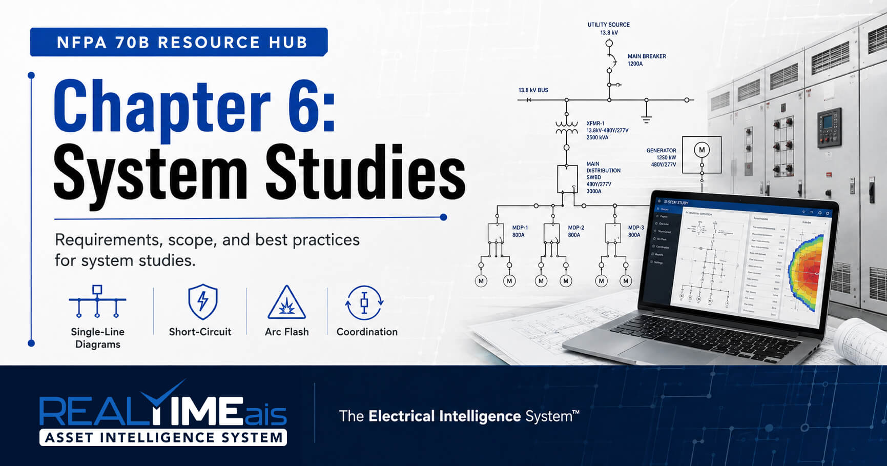
A single-line diagram (also called a one-line diagram) is the schematic representation of your entire electrical distribution system. It shows the utility service entrance, main switchgear, distribution panels, feeders, protective devices, transformers, motor control centers, and the relationships between them.
NFPA 70B requires that every facility maintain a current, accurate single-line diagram that reflects the as-built electrical system. This is not a suggestion – it is a foundational requirement because every system study depends on the single-line diagram for its input data. An inaccurate single-line diagram produces inaccurate study results, which produce inaccurate safety data.
The most common problem in practice: the single-line diagram was drawn during original construction and has never been updated. Over the years, the facility has added loads, replaced transformers, upgraded protective devices, changed utility service, and installed generators – none of which are reflected on the diagram. Every calculation based on that drawing is wrong.
2.2 Short-Circuit Studies
A short-circuit study calculates the maximum available fault current at every point in the electrical distribution system. This data is essential for verifying that protective devices are rated to safely interrupt the maximum fault current at their location. If a breaker is rated for 25,000 amps but actual available fault current is 35,000 amps, the breaker may not clear the fault safely – potentially resulting in equipment failure, fire, or arc flash.
Short-circuit study results are also one of the primary inputs to the incident energy analysis. Fault current magnitude directly affects the intensity and duration of an arc flash event, which determines the incident energy level on arc flash labels and drives PPE requirements.
2.3 Coordination Studies
A coordination study evaluates whether the protective devices in the system are configured to operate in the correct sequence. Proper coordination means the device closest to a fault trips first, isolating the faulted circuit while keeping the rest of the system energized. Poor coordination means an upstream device may trip first, causing an unnecessary outage affecting a much larger portion of the facility.
Coordination is especially critical in facilities where certain loads cannot tolerate interruption – hospitals, data centers, continuous manufacturing processes, and food processing lines.
2.4 Incident Energy Analysis (Arc Flash Study)
The incident energy analysis calculates the thermal energy released during an arc flash event at each point in the electrical system. The study produces incident energy values (calories per square centimeter) that determine the arc flash boundary, required arc-rated PPE, and information on arc flash labels.
The arc flash study is the direct bridge between NFPA 70B (equipment maintenance) and NFPA 70E (worker safety). It uses data from the short-circuit study and single-line diagram as inputs, and its outputs drive the safety requirements that protect every worker who interacts with the equipment.
3. The Five-Year Mandatory Interval
The NFPA 70B 2026 edition codified a critical requirement: all system studies must be performed at intervals of no more than five years.
This applies to short-circuit studies, coordination studies, and incident energy analyses. The five-year clock starts from the date of the most recent study. If your last arc flash study was performed in 2020, you are already overdue under the 2026 edition.

Check Your Study Dates Now
Pull the dates on your most recent short-circuit study, coordination study, and incident energy analysis for every facility. If any study is older than five years from today, you are out of compliance with NFPA 70B-2026. Schedule updates immediately.
3.1 System Change Triggers
The five-year interval is the maximum – but system changes can trigger mandatory interim updates much sooner. The 2026 edition requires updated diagrams and revised studies whenever any of the following occur:
| System Change | Why It Triggers an Update |
|---|---|
| Utility service upgrade or change | Changes available fault current at service entrance, cascading through the entire system. |
| Addition of on-site generation | Generators contribute additional fault current that may exceed existing device ratings and change incident energy. |
| Transformer replacement or re-tap | Changes impedance values affecting downstream fault current calculations. |
| Protective device replacement | New devices with different trip characteristics affect coordination and arc flash clearing times. |
| Protective device setting changes | Adjusted trip/delay settings change coordination and arc flash duration. |
| Significant load additions | Large new loads change system characteristics and may affect fault current contribution. |
| Electrical system reconfiguration | Moving feeders, adding panels, changing bus configurations invalidates existing study data. |
| Utility fault current notification | Utility changes to available fault current require reverification of all downstream calculations. |
Organizations need a documented process for tracking system changes and evaluating whether each change triggers a study update. Without this, changes accumulate silently and the single-line diagram drifts further from reality.

How REALTIMEais Helps
REALTIMEais tracks system study dates by facility and by system with automated alerts when the five-year interval approaches. When system modifications are documented – a transformer replacement, a protective device change, a utility upgrade – the system automatically flags affected studies for review. REALTIME Risk manages arc flash study data while REALTIME Tool manages equipment maintenance data, in one integrated environment.
4. Single-Line Diagram Requirements Under NFPA 70B
A compliant single-line diagram must include:
| Element | Required Information |
|---|---|
| Utility Service | Available fault current, service voltage, metering location, main protective device ratings. |
| Transformers | kVA rating, primary/secondary voltages, impedance, winding configuration (delta/wye), tap settings. |
| Switchgear | Bus ratings, main/tie breaker ratings, interrupting capacity, protective device settings. |
| Distribution Panels | Panel designation, voltage, phase configuration, main breaker rating, feeder source. |
| MCCs | Bus rating, starter sizes, motor HP ratings, protective device settings per bucket. |
| Feeders/Cables | Conductor size, type, length, conductors per phase. Cable routing for impedance calculations. |
| Protective Devices | Device type, manufacturer, model, frame/trip rating, interrupting rating, current settings. |
| Generators | kW/kVA rating, voltage, subtransient reactance, grounding, transfer switch details. |
| Grounding System | System grounding type, grounding electrode configuration. |
The critical requirement is currency. The diagram must reflect the system as it exists today – not as it was built, not as it was designed, but as it is actually configured right now. Every modification must be reflected.
5. The Five Most Common Chapter 6 Failures
Failure 1: The Single-Line Diagram Has Never Been Updated
The original construction drawing is the only version. Ten, twenty, sometimes thirty years of modifications are not reflected. The diagram is fiction. Every study based on it produces inaccurate results, and every arc flash label generated from those studies displays incorrect information.
Failure 2: System Studies Are Ten or More Years Old
Many facilities performed an arc flash study once – often after an OSHA citation or insurance requirement – and never updated it. The utility has changed fault current. Equipment has been replaced. Loads have been added. The study results no longer reflect reality, and workers rely on outdated arc flash labels every day.
Failure 3: No Process for Tracking System Changes
Even organizations with recent studies often have no process for identifying changes that trigger updates. A transformer gets replaced, a utility upgrade occurs, a technician adjusts a breaker setting – none flagged as study triggers. The diagram drifts and studies become stale.
Failure 4: Studies Exist but Results Are Not Applied
Some organizations commission studies that sit in a filing cabinet and are never acted on. The arc flash study was completed but labels were never updated. The coordination study found problems but settings were never adjusted. Having a study you don’t act on may be worse than not having one – because it demonstrates you knew about the hazard and chose not to address it.
Failure 5: The Single-Line Diagram Is Not Accessible
A diagram that exists only as a large-format paper drawing rolled up in an engineering office is functionally inaccessible. Technicians, safety managers, and contractors all need it. The diagram must be digitized and accessible within the maintenance and safety management system.
6. How to Bring Your Facility into Chapter 6 Compliance
Step 1: Audit Your Current Single-Line Diagram
Compare your existing diagram against the actual system. Walk the facility and mark every discrepancy: equipment added, replaced, removed, or reconfigured. If no diagram exists, you need a full electrical survey.
Step 2: Commission an Updated Single-Line Diagram
Engage a qualified electrical engineering firm to produce a current, accurate diagram. It must include all elements listed in Section 4. Request digital deliverables (AutoCAD/PDF) and a format importable into your maintenance system.
Step 3: Perform or Update All Three System Studies
With the updated diagram, commission the three studies: short-circuit analysis, protective device coordination, and incident energy analysis. These are typically performed as an integrated package. Ensure studies use current IEEE 1584 for incident energy calculations.
Step 4: Apply the Results
Update all arc flash labels. Adjust protective device settings per coordination study. Replace underrated devices per short-circuit study. Update PPE requirements and approach boundaries. Communicate changes to all affected personnel.
Step 5: Establish a Tracking System
Document study completion dates and establish tracking for the five-year interval and system change triggers. A digital platform that automates this tracking eliminates the risk of missed intervals or overlooked changes.
How REALTIMEais Helps
REALTIMEais manages the complete Chapter 6 lifecycle. REALTIME Risk stores arc flash data by asset with incident energy, PPE, and boundaries. REALTIME Tool tracks the five-year interval with automated alerts and flags system changes requiring study review. When a transformer replacement is documented, the system automatically notifies that affected studies need review. No manual tracking. No missed intervals.

Are Your System Studies Current?
If your last arc flash study is more than five years old, or if your single-line diagram doesn’t match your actual system, you are out of compliance with NFPA 70B-2026. REALTIMEais offers a free compliance assessment that evaluates your system study status and identifies your highest-priority gaps.
Request a Free System Study Assessment
Call 866-558-4313 | Visit realtimeais.com/demo

About REALTIMEais
REALTIMEais is The Electrical Intelligence System™ — a SaaS platform purpose-built for electrical asset management, NFPA 70B compliance, arc flash safety, and predictive maintenance. Unlike generic CMMS platforms, REALTIMEais was designed from the ground up for the specific requirements of electrical equipment maintenance, with live integrations to FOTRIC AI infrared cameras, GraceSense hot-spot monitoring sensors, ETAP power system analysis software, and Inductive Automation Ignition SCADA systems.
Founded by Steve Abbott, a 30+ year veteran of electrical safety consulting, REALTIMEais combines deep domain expertise with modern software architecture to deliver Quicker, Simpler, Safer compliance for facilities of every size.

Steven J. Abbott
-CEO-
NFPA 70B Hub

Free Resource
NFPA 70B
Compliance Checklist
Compliance Checklist
Evaluate your EMP, documentation, condition assessments, maintenance intervals, system studies, and audit readiness.
Browse by Topic
Not sure where you stand?
Schedule the free readiness audit and receive the checklist as part of the meeting flow.
More NFPA 70B Resources

Schedule Your Free Readiness Audit and
Get Your NFPA 70B Compliance Checklist
As a certified NFPA 70B specialist, I'll help you understand the latest requirements, identify gaps in your current Electrical Maintenance Program, and outline a clear path to compliance. We'll discuss your specific facility, equipment, and challenges in a personalized web meeting.
- A better understanding of your current NFPA 70B compliance state.
- Identification of key areas for improvement in your EMP.
- Practical next steps to build a robust, audit-ready program.
- A free NFPA 70B Compliance Checklist to guide your efforts.
Don't navigate the complexities of NFPA 70B alone.
Let's ensure your facility is safe, compliant, and efficient.

Book a time that works for you